Built Right
Understanding code behind residential ventilation — why they exist, what they require, and how they shape every component from the dryer connection to the roofline.
Published by InOvate Engineering | Last reviewed: Mar 2026
Count on InOvate products for advanced design performance that meets or exceeds all building code.
Top that with
advanced manufacturing processes and best in class materials, and you have durable components that stand the test of time.
Dryer Exhaust Systems
Clothes dryer exhaust is the most heavily regulated mechanical system in a home, and for good reason. The U.S. Fire Administration estimates that clothes dryers cause nearly 3,000 residential fires each year, and the leading contributing factor is failure to clean or maintain the venting system. The codes governing dryer exhaust exist to minimize lint accumulation, ensure adequate airflow, and keep the exhaust path independent from other building systems.
The International Residential Code (IRC) Section M1502 and the International Mechanical Code (IMC) Section 504 are the two primary code bodies. The IRC applies to one- and two-family dwellings and townhomes; the IMC applies to commercial and multi-family construction. Most local jurisdictions adopt one or both, sometimes with amendments — so the local authority having jurisdiction (AHJ) always has the final word.

Key Requirements
One of the least understood requirements is the equivalent duct length label. Building codes require that the total equivalent length of the exhaust system — including all fittings — be documented and posted at the dryer connection point. This ensures that future appliance installers and service technicians know the system's capacity before connecting a new dryer with different performance characteristics.
Ventilation & Indoor Air Quality
As homes become tighter and more energy-efficient, the need for controlled mechanical ventilation has moved from a best practice to a code requirement. Modern residential construction cannot rely on natural infiltration — the air leakage that older homes depended on — to maintain indoor air quality. Codes now mandate engineered systems that introduce fresh air and exhaust stale air at controlled rates.
ASHRAE Standard 62.2 has become the backbone of residential ventilation requirements in many jurisdictions. It defines minimum ventilation rates calculated from floor area and bedroom count, and it distinguishes between local exhaust (point-source removal from kitchens and baths) and whole-building ventilation (continuous dilution of indoor pollutants). The standard has been incorporated by reference into the IRC and several state energy codes.
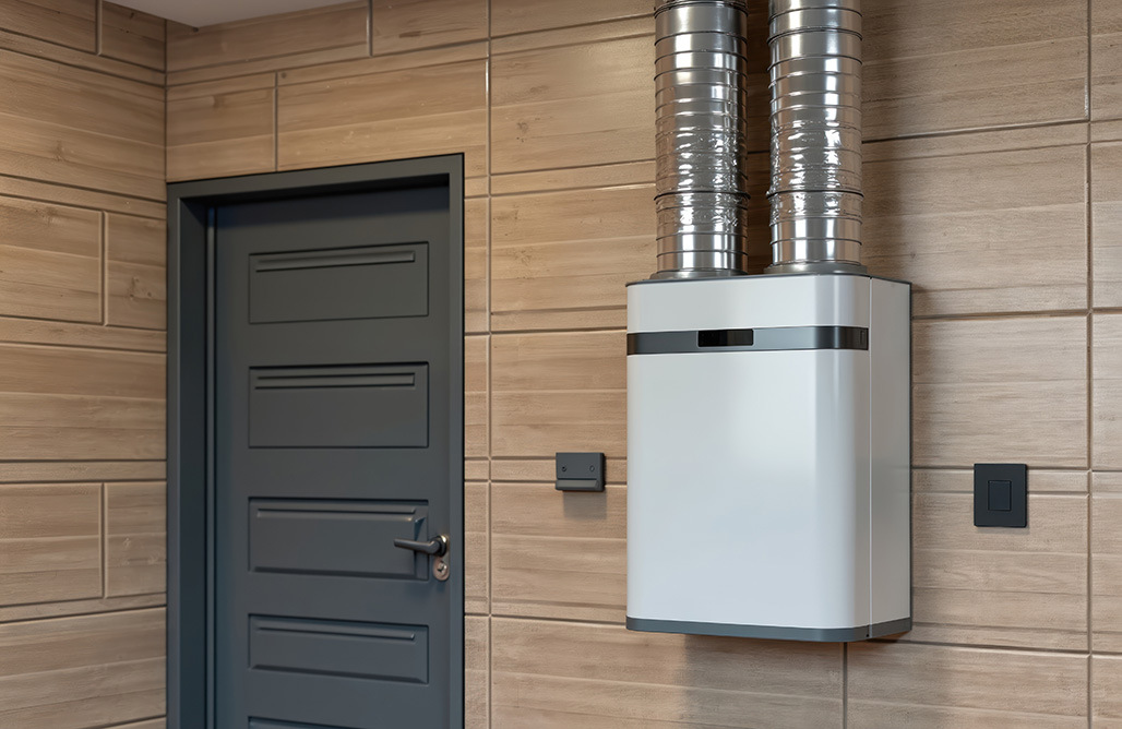
Energy Recovery Ventilators (ERVs) and Heat Recovery Ventilators (HRVs) are the most common compliance paths for whole-building ventilation. These systems exchange heat (and in the case of ERVs, moisture) between the incoming and outgoing air streams, recovering energy that would otherwise be lost. They require both a fresh air intake and an exhaust port on the building exterior — and the placement of these ports is heavily regulated.
The exterior termination ports for these systems are fundamentally different from dryer exhaust. They must be engineered for bidirectional or intake-specific airflow patterns, sealed against weather intrusion, and mounted in locations that satisfy the separation distances from exhaust outlets. Using a general-purpose vent cap for an ERV or fresh air intake creates compliance issues at inspection.
Roof Penetrations & Terminations
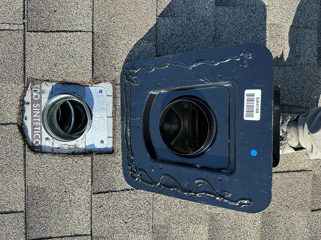
Every roof penetration is a potential failure point for the building envelope. Water intrusion through improperly flashed vent penetrations is the leading cause of structural damage in residential roofing — and it goes undetected until the damage is extensive. The codes governing roof terminations address both the weatherproofing of the penetration itself and the performance of the vent cap on top of it.
For dryer exhaust specifically, the challenge is more nuanced. Conventional roof vents designed for bathroom fans or plumbing stacks were never intended to handle dryer exhaust. Their internal baffles, screens, and narrow passageways choke lint-laden air, creating the same backpressure and accumulation problems that the exhaust codes were written to prevent. A purpose-built dryer roof cap provides a clear, low-restriction exhaust path while maintaining effective backdraft protection.
When soffit-area termination is unavoidable — as it is for upper-floor dryers in center-of-home locations — the solution is not to vent into the soffit but to direct exhaust downward and outward, away from the soffit intake. Purpose-built soffit termination components accomplish this by angling the exhaust trajectory clear of the recirculation zone.
Wall Penetrations & Terminations
Wall penetrations for vent terminations are the most common source of moisture intrusion in residential construction. Every hole through the exterior wall breaches the weather-resistant barrier (WRB) — the critical layer that protects the structure from bulk water. If that breach isn't properly integrated with the WRB, flashing tape, and sealant, water finds its way into the wall cavity. The resulting damage takes years to manifest and is expensive to repair.
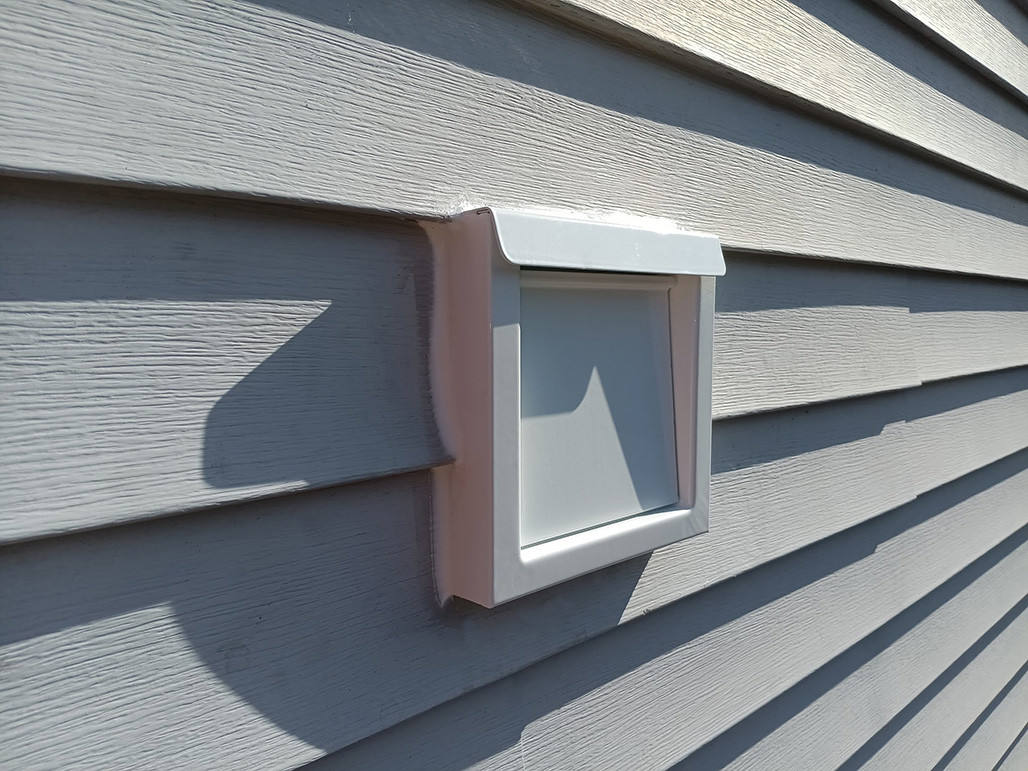
The building codes addressing wall terminations govern several overlapping concerns: maintaining the WRB around the penetration (IRC R703.1), locating the termination at code-compliant distances from grade, property lines, and operable openings (IRC M1502.3), and ensuring that the vent cap itself functions correctly — backdraft protection for exhaust, weather sealing for intake, and pest prevention without lint-catching screens.
What the codes don't explicitly address — but what experienced builders know — is that material quality determines long-term compliance. A plastic vent cap that meets code on installation day degrades under UV exposure within a few years, losing its seal, warping its damper, and allowing pest intrusion. Premium metal construction maintains its performance characteristics over the life of the structure, avoiding callbacks and ensuring the termination continues to satisfy the original code intent decades after installation.
Fire-Rated Assemblies
In multi-family housing, townhomes, and any dwelling with attached garages, fire-rated wall and floor assemblies are required to slow the spread of fire between units and between the garage and living space. Every penetration through a rated assembly — including dryer exhaust connections — must be firestopped to maintain the assembly's fire-resistance rating. A single unprotected penetration voids the entire wall's rating and creates a deadly pathway for flame and smoke.
IRC Section R302.4 requires that penetrations through fire-rated assemblies be protected with an approved through-penetration firestop system — one that has been tested and classified by a nationally recognized testing laboratory (NRTL) such as UL. The system must maintain the fire-resistance rating of the assembly and must be installed in strict accordance with the conditions of the listing.
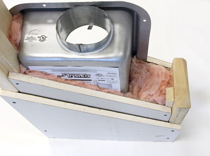
This is where generic solutions fall short. To pass inspection in a rated wall, you need more than a duct through drywall — you need a UL-classified system with documented F and T ratings for the specific wall configuration. The F rating measures how long the system prevents flame passage through the penetration. The T rating measures how long the surface temperature on the unexposed side remains below dangerous levels. Both are required to demonstrate that the penetration won't compromise the assembly's ability to protect occupants during a fire.
This is a genuine differentiator for builders. Most generic duct-through-wall solutions have no UL-classified firestop path, which means the installer must find a compatible third-party firestop system and hope it's been tested for the specific penetration size and configuration. A product that ships with its own UL classification eliminates that guesswork and significantly reduces inspection risk.
Energy Code & Air Sealing
Energy codes have tightened dramatically over the past decade. What was once a loosely enforced suggestion to "seal penetrations" is now a tested, verified requirement with real consequences for failing. The International Energy Conservation Code (IECC) and IRC Section N1102 require that every penetration through the building envelope — including ventilation ducts, exhaust vents, and intake ports — be sealed, caulked, gasketed, or weather-stripped to limit air leakage.
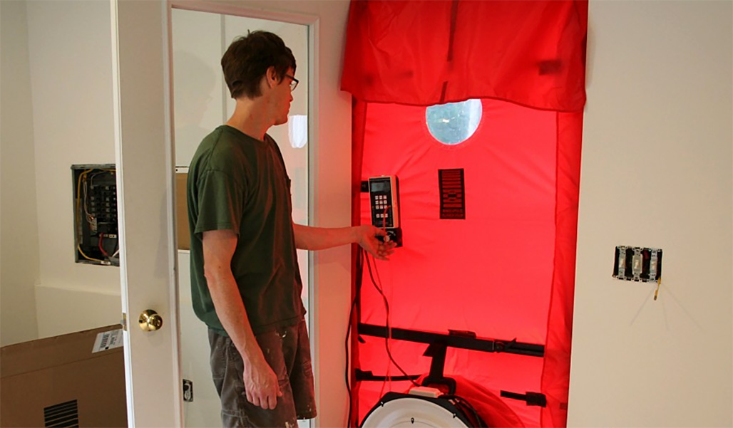
The enforcement mechanism is the blower door test — a pressurization test that measures the total air leakage of the building envelope, expressed in air changes per hour at 50 Pascals (ACH50). The 2021 IECC requires a maximum of 3 ACH50 in climate zones 3–8, and 5 ACH50 in zones 1–2. Every unsealed vent penetration contributes to that number, and builders who treat vent installation as an afterthought find themselves failing the blower door test and scrambling to identify leaks.
Poorly sealed vent penetrations are thermal bridges — they allow conditioned air to escape and unconditioned air to enter, reducing the effective R-value of the wall or roof assembly. In heating-dominated climates, warm moist interior air migrating through an unsealed penetration condenses inside the wall cavity, creating the same moisture problems that the WRB is designed to prevent from the exterior side.
Two Decades of Tightening Standards
Building codes are living documents. The ICC publishes new editions on a three-year cycle, and each cycle reflects lessons learned from fires, building failures, energy research, and field experience. The dryer exhaust and mechanical ventilation sections have evolved significantly since 2003 — with requirements becoming more specific, more restrictive, and more focused on real-world performance. The timeline below traces the key changes relevant to residential ventilation.
Note: Local jurisdictions adopt these codes on their own schedules, often one or two cycles behind the current ICC edition. Always verify which code edition is in effect with your local authority having jurisdiction (AHJ).
Important Code Sections
Code Question?
The awesome InOvate engineering team enjoys helping builders, contractors, and inspectors navigate building code requirements for residential ventilation every day.
Contact Team InOvate